السلام عليكم ورحمته تعالى وبركاته
كان يراودي اقتراح مهم جدا للغاية لا اعلم هل ساجد فيه تجاوبا من العائلة المتواجدة في المنتدى او لا
اقتراحي ان نقوم بتصميم طائرة بالسولييد وركس لكن ان لا تكون شكلية اي نقوم بتصميم محركاتها ثم اجزائها ونقوم بتركيبها ثم العمل عليها ب motion و simulation
اي بتطبيق كل ما يتعلق به او يمكن التطبيق عليه بالسولييد وركس
اتمنى ان اجد اقبالا كبيرا
شكرا لكم
نظراً لأن كل اقتراحات الزملاء بالنسبة لنا هي اقتراحات هامة، فلذلك يعتبر عنوان الموضوع الحالي لا يعبر عن محتوى الموضوع ولذلك تم تعديل العنوان لكي يعبر عن محتواه.
بالنسبة لمضوع تصميم طائرة كاملة بمحركاتها، فبالمصري “ماكانش حد غلب” لأنها أكيد ليست بهذه السهولة. أنا عندي فكرة قد تكون أكثر عملية وفعلاً قد ننجح في عملها لو أردنا، بل وأيضاً قد ننجح في إنتاجها، وهي الطائرة الهليوكبتر الصغيرة “تشبه اللعبة ولكنها ليست لعبة” مثل هذه
وهي موجودة بماحلات اللعب وسعرها بدأ يرخص نسبياً بالماضي، ولا تفرق كثيراً عن الطائرات التي يستخدمها بعض سكان المناطق الجبلية والنائية في كندا وأمريكا، أقصد إذا تمكنا من عمل النموذج الصغير، فيمكن تكبير النموذج. أو حتى إنتاجها كلعبة كمشروع قد يدر ربح على منفذه، وكذلك ربما لاحقاً يمكن تطويرها لتصبح طائرة بدون طيار تصنيع محلي يمكن أن تستخدم في العمليات الكشفية والتصوير عن بعد.
جمبل الفكرة ولكن لابد من التعاون ونبدأ في العمل فالعمل بالتعاون شكرا لك اخي محمد
زى دى مثلا ؟؟؟؟
الموديل ده كان من grabcad و انا عملت عليه شغل ال actuator sizing مواتير و عزم و thrust force بمعنى أصح شغل ال dynamics كله
غير كله فيه كورس على النت لرسم الطائرة الاباتشي موجود بس محتاج بحث شوية - انا شوفتوه من سنين كده بس مش فاكر فين - رسم كامل للطائرة من A to Z
بأقولك آيه، انت الموضوع بتاع رسم الأباتشي ده لازم تجيبه يعني لازم تجيبه، أنا دورت عليه وما لاقيتهوش، هاتوا من تحت الأرض يا هندسة الله يبارك لك، أنت أبو المهام القيصرية ![]()
ويبدو من كلامك السابق إنك لك خبرة في موضوع ديناميكا الهواء، مر لنا على الموضوع ده وسمعنا رأيك
http://www.almohandes.org/vb/f142/t78569/
السلام عليكم
اليكم رسمة بالسوليد ووركس ل helicopter-rotor
ايش رايكم نعملها motion
شكرا لكم
اليكم ما يلي
في المرفقات
اليكم ما يلي
واليكم من grabcad
http://grabcad.com/library/hk-450-rc-helicopter
ولكن نحن الهدف التعلم و الاستفادة كيقية تطبيق motion و simulation
electrical
ليس الهدف ان ترسم وخلاص لا لابد ان يكون لديك مفاهيم وتحاليل فالمهندس هو اساسا يقوم بتحليل مشكل معين وتبسيط للمسالة كي يتمكن من الانطلاق فيه انا لما اقترحت هذا الاقتراح نظرا لشموليته في المكونات حتى يكون الاستفادة واضحة وهامة واتمنى ان يكون كلامي ليش فيه خروج من قوانين المنتدى شكرا لكم
مش فاكر و الله انا شوفتووا فين - بس أنا أخطات فيه أسمه – إسم الكورس the f-16 step-by-step video tutorial و دى بقي مهمة صديقنا عزام
الطائرة ده معمولة جاهزة على grapcad ممكن تستفيد من الموديل ده و نستخدمه على طول و نعمل الشغل عليه - هو موجود إصدار 2012
أما بقي موضوع ديناميكا الهواء انا مليش فيه أو بمعنى "بطيخ فيه " كل اللى أعرفه شوية معلومات على قدي فى motion simulation
ما انت يابني لساك قايل إنك عملت شغل الدينامكيس كله  وحسابات Thrust دي ماهي تبعها بردو ولا ده شغل “فلسعة”؟؟
ماشي ماشي أخلص أمتحانات بس
أسأل الله أن يوفقك دائماً، ويا رب تطلع الأول على الدفعة ![]()
[CENTER]Hosepipes, helicopters and conveyor belts
1. Hosepipe
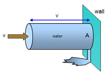 You can appreciate that if you are hit by a fast moving stream of water from a hose pipe you experience a force - if this hosepipe is a water cannon then the force could be great enough to knock you over.
Consider a hosepipe of cross sectional area A that gives a jet of water of velocity v. If this hits a vertical wall and loses all its momentum then in one second a jet of length v will hit the wall and so:
Mass of water striking the wall per second = rvA where r is the density of the water
Force on wall = rate of change of momentum of water = change of momentum per second = [rvA]v = rv2A
Force due to water jet = rAv2
[COLOR=#000000] [B]Example problem[/b]
A water cannon has a cross sectional area of 25 cm2 (25x10-4 m2). It ejects a jet of water (density 1000 kgm-3) at a speed of 20 ms-1.
Calculate the force in the jet.
Force = rAv2 = 1000x25x10-4x202 = 1000 N [/color]
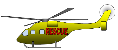 2. The hovering helicopter
Imagine a helicopter hovering above the ground. The blades on the rotor are angled slightly so that as they spin round they thrust a column of air downwards - it is this column of air moving vertically that keeps the helicopter up. The faster the blades rotate and the larger they are the bigger the lift, so large helicopters need large blades or even two rotors.
Now as before for the water jet force = rate of change of momentum and so for the helicopter to hover the momentum change per second of the air column must be equal to the weight of the helicopter.
Using both Newton’s second and third laws:
[COLOR=#000000] mg = [FONT=symbol]rp[/font]r2v2 [/color]
so for a helicopter of mass 4500 kg, air of density 1.2 kgm-3 and rotor blades 6.2 m in radius the vertical speed of the air column produced by the rotor blades must be 17 ms-1.
The power of the helicopter
Remember that Power = Force x Velocity however in this case the velocity of the air column is being increased from zero to v and so the average velocity is v/2. This gives the power as:
Power = Force x average velocity = rpr2v2 x v/2 = rpr2v3
Some examples of powers: Lynx helicopter power range 670 kW - 835 kW Power boat = 112 kW
3. Conveyor belt and moving walkway
(This description could apply either to a person stepping onto a horizontal moving walkway or to sand being tipped onto a conveyor belt)
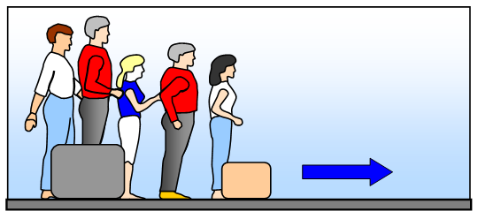
Imagine that people of total mass m step onto a moving walkway every second. If the velocity of the walkway is v then:
gain in momentum per second = mv
but this is the rate of change of momentum and therefore the force needed to move the belt is:
Force in conveyor belt :- space Force = mv
[/center]
[CENTER][CENTER] THE THEORY OF AIRCRAFT AERODYNAMICS
     [/center]
     [B]AERODYNAMICS IS A BRANCH OF DYNAMICS CONCERNED WITH STUDYING THE          MOTION OF AIR, PARTICULARLY WHEN IT INTERACTS WITH A MOVING OBJECT SUCH AS AN AIRCRAFT.         [/b]

                             [CENTER][IMG]http://www.aviationexplorer.com/Aircraft%20Aerodynamics/aerodynamic_center_NASA.gif[/IMG][/center]

                            [CENTER][IMG]http://www.aviationexplorer.com/airplane_surfaces.gif[/IMG][/center]

                            [CENTER][IMG]http://www.aviationexplorer.com/Aircraft%20Aerodynamics/wingsection.jpg[/IMG][/center]

                                                            [B]Aerodynamics is closely related to fluid dynamics
            and gas dynamics, with much theory shared between them. [/b]

             Aerodynamics is often used synonymously with gas  dynamics, with the difference being that gas dynamics applies to all  gases. Understanding the motion of air (often called a flow field)  around an object enables the calculation of forces and moments acting on  the object. Typical properties calculated for a flow field include  velocity, pressure, density and temperature as a function of position  and time. By defining a control volume around the flow field, equations  for the conservation of mass, momentum, and energy can be defined and  used to solve for the properties. The use of aerodynamics through  mathematical analysis, empirical approximation and wind tunnel  experimentation form the scientific basis for heavier-than-air flight.
             Aerodynamic problems can be identified in a number of  ways. The flow environment defines the first classification criterion.  External aerodynamics is the study of flow around solid objects of  various shapes. Evaluating the lift and drag on an airplane, the shock  waves that form in front of the nose of a rocket or the flow of air over  a hard drive head are examples of external aerodynamics. Internal  aerodynamics is the study of flow through passages in solid objects. For  instance, internal aerodynamics encompasses the study of the airflow  through a jet engine or through an air conditioning pipe.
             The ratio of the problem's characteristic flow speed  to the speed of sound comprises a second classification of aerodynamic  problems. A problem is called subsonic if all the speeds in the problem  are less than the speed of sound, transonic if speeds both below and  above the speed of sound are present (normally when the characteristic  speed is approximately the speed of sound), supersonic when the  characteristic flow speed is greater than the speed of sound, and  hypersonic when the flow speed is much greater than the speed of sound.  Aerodynamicists disagree over the precise definition of hypersonic flow;  minimum Mach numbers for hypersonic flow range from 3 to 12. Most  aerodynamicists use numbers between 5 and 8.
             The influence of viscosity in the flow dictates a  third classification. Some problems involve only negligible viscous  effects on the solution, in which case viscosity can be considered to be  nonexistent. The approximations to these problems are called inviscid  flows. Flows for which viscosity cannot be neglected are called viscous  flows.
                                                     [CENTER][IMG]http://www.aviationexplorer.com/Aircraft%20Aerodynamics/foil.gif[/IMG][/center]
                                                 History
             Images and stories of flight have appeared throughout  recorded history, with perhaps the most noted of these being the story  of Icarus and Daedalus. Although observations of some aerodynamic  effects like wind resistance (a.k.a. drag) were recorded by the likes of  Aristotle and Galileo Galilei, very little effort was made to develop  governing laws for understanding the nature of flight prior to the 17th  century.
             Sir Isaac Newton was the first person to develop a  theory of air resistance, arguably making him the world's first  aerodynamicist. As part of that theory, Newton believed that drag was  due to the dimensions of a body, the density of the fluid, and the  velocity raised to the second power. These beliefs all turned out to be  correct for low flow speeds. Newton also developed a law for the drag  force on a flat plate inclined towards the direction of the fluid flow.  Using F for the drag force, ρ for the density, S for the area of the  flat plate, V for the flow velocity, and θ for the inclination angle,  his law is expressed below.
             Unfortunately, this equation is completely incorrect  for the calculation of drag (unless the flow speed is hypersonic). Drag  on a flat plate is closer to being linear with the angle of inclination  as opposed to acting quadratically. This formula can lead one to believe  that flight is more difficult than it actually is, and it may have  contributed to a delay in manned flight.
             [CENTER] [/center]
             Sir George Cayley is credited as the first person to  separate the forces of lift and drag which are in effect on any flight  vehicle. Cayley believed that the drag on a flying machine must be  counteracted by a means of propulsion in order for level flight to  occur. Cayley also looked to nature for aerodynamic shapes with low  drag. One of the shapes he investigated were the cross-sections of  trout. Although this may appear a bit comical in retrospect, the bodies  of fish are actually shaped to produce very low resistance as they  travel through water. As such, their cross-sections are sometimes very  close to that of modern low drag airfoils.
             These empirical findings led to a variety of air  resistance experiments on various shapes throughout the 18th and 19th  centuries. Drag theories were developed by Jean le Rond d'Alembert,  Gustav Kirchhoff, and Lord Rayleigh. Equations for fluid flow with  friction were developed by Claude-Louis Navier and George Gabriel  Stokes. To simulate fluid flow, many experiments involved immersing  objects in streams of water or simply dropping them off the top of a  tall building. Towards the end of this time period Gustave Eiffel used  his Eiffel Tower to assist in the drop testing of flat plates.
             Of course, a more precise way to measure resistance  is to place an object within an artificial, uniform stream of air where  the velocity is known. The first person to experiment in this fashion  was Francis Herbert Wenham, who in doing so constructed the first wind  tunnel in 1871. Wenham was also a member of the first professional  organization dedicated to aeronautics, the Royal Aeronautical Society of  Great Britain. Objects placed in wind tunnel models are almost always  smaller than in practice, so a method was needed to relate small scale  models to their real-life counterparts. This was achieved with the  invention of the dimensionless Reynolds number by Osbourne Reynolds.  Reynolds also experimented with laminar to turbulent flow transition in  1883.
             By the late 19th century, two problems were  identified before heavier-than-air flight could be realized. The first  was the creation of low-drag, high-lift aerodynamic wings. The second  problem was how to determine the power needed for sustained flight.  During this time, the groundwork was laid down for modern day fluid  dynamics and aerodynamics, with other less scientifically inclined  enthusiasts testing various flying machines with little success.
             In 1889, Charles Renard, a French aeronautical  engineer, became the first person to reasonably predict the power needed  for sustained flight. Renard and German physicist Hermann von Helmholtz  explored the wing loading of birds, eventually concluding that humans  could not fly under their own power by attaching wings onto their arms.  Otto Lilienthal, following the work of Sir George Cayley, was the first  person to become highly successful with glider flights. Lilienthal  believed that thin, curved airfoils would produce high lift and low  drag.
             Octave Chanute provided a great service to those  interested in aerodynamics and flying machines by publishing a book  outlining all of the research conducted around the world up to 1893.  With the information contained in that book and the personal assistance  of Chanute himself, the Wright brothers had just enough knowledge of  aerodynamics to fly the first manned aircraft on December 17, 1903, just  in time to beat the efforts of Samuel Pierpont Langley. The Wright  brothers' flight confirmed or disproved a number of aerodynamics  theories. Newton's drag force theory was finally proved incorrect. The  first flight led to a more organized effort between aviators and  scientists, leading the way to modern aerodynamics.
             During the time of the first flights, Frederick W.  Lanchester, Martin Wilhelm Kutta, and Nikolai Zhukovsky independently  created theories that connected circulation of a fluid flow to lift.  Kutta and Zhukovsky went on to develop a two-dimensional wing theory.  Expanding upon the work of Lanchester, Ludwig Prandtl is credited with  developing the mathematics behind thin-airfoil and lifting-line theories  as well as work with boundary layers. Prandtl, a professor at Gottingen  University, instructed many students who would play important roles in  the development of aerodynamics like Theodore von Kármán and Max Munk.
             As aircraft began to travel faster, aerodynamicists  realized that the density of air began to change as it came into contact  with an object, leading to a division of fluid flow into the  incompressible and compressible regimes. In compressible aerodynamics,  density and pressure both change, which is the basis for calculating the  speed of sound. Newton was the first to develop a mathematical model  for calculating the speed of sound, but it was not correct until  Pierre-Simon Laplace accounted for the molecular behavior of gases and  introduced the heat capacity ratio. The ratio of the flow speed to the  speed of sound was named the Mach number after Ernst Mach, who was one  of the first to investigate the properties of supersonic flow which  included Schlieren photography techniques to visualize the changes in  density. William John Macquorn Rankine and Pierre Henri Hugoniot  independently developed the theory for flow properties before and after a  shock wave. Jakob Ackeret led the initial work on calculating the lift  and drag on a supersonic airfoil. Theodore von Kármán and Hugh Latimer  Dryden introduced the term transonic to describe flow speeds around Mach  1 where drag increases rapidly. Because of the increase in drag  approaching Mach 1, aerodynamicists and aviators disagreed on whether  manned supersonic flight was achievable.
             On September 30, 1935 an exclusive conference was  held in Rome with the topic of high velocity flight and the possibility  of breaking the sound barrier.Participants included von Kármán, Prandtl,  Ackeret, Eastman Jacobs, Adolf Busemann, Geoffrey Ingram Taylor,  Gaetano Arturo Crocco, and Enrico Pistolesi. The new research presented  was impressive. Ackeret presented a design for a supersonic wind tunnel.  Busemann gave perhaps the best presentation on the need for aircraft  with swept wings for high speed flight. Eastman Jacobs, working for  NACA, presented his optimized airfoils for high subsonic speeds which  led to some of the high performance American aircraft during World War  II. Supersonic propulsion was also discussed. The sound barrier was  broken using the Bell X-1 aircraft twelve years later, thanks in part to  those individuals.
             By the time the sound barrier was broken, much of the  subsonic and low supersonic aerodynamics knowledge had matured. The  Cold War fueled an ever evolving line of high performance aircraft.  Computational fluid dynamics was started as an effort to solve for flow  properties around complex objects and has rapidly grown to the point  where entire aircraft can be designed using a computer.
             With some exceptions, the knowledge of hypersonic  aerodynamics has matured between the 1960s and the present decade.  Therefore, the goals of an aerodynamicist have shifted from  understanding the behavior of fluid flow to understanding how to  engineer a vehicle to interact appropriately with the fluid flow. For  example, while the behavior of hypersonic flow is understood, building a  scramjet aircraft to fly at hypersonic speeds has seen very limited  success. Along with building a successful scramjet aircraft, the desire  to improve the aerodynamic efficiency of current aircraft and propulsion  systems will continue to fuel new research in aerodynamics.
             Transonic flow
              The term Transonic refers to a range of velocities  just below and above the local speed of sound (generally taken as Mach  0.8–1.2). It is defined as the range of speeds between the critical Mach  number, when some parts of the airflow over an aircraft become  supersonic, and a higher speed, typically near Mach 1.2, when all of the  airflow is supersonic. Between these speeds some of the airflow is  supersonic, and some is not.
             Supersonic flow
              Supersonic aerodynamic problems are those involving  flow speeds greater than the speed of sound. Calculating the lift on the  Concorde during cruise can be an example of a supersonic aerodynamic  problem.
             Supersonic flow behaves very differently from  subsonic flow. Fluids react to differences in pressure; pressure changes  are how a fluid is "told" to respond to its environment. Therefore,  since sound is in fact an infinitesimal pressure difference propagating  through a fluid, the speed of sound in that fluid can be considered the  fastest speed that "information" can travel in the flow. This difference  most obviously manifests itself in the case of a fluid striking an  object. In front of that object, the fluid builds up a stagnation  pressure as impact with the object brings the moving fluid to rest. In  fluid traveling at subsonic speed, this pressure disturbance can  propagate upstream, changing the flow pattern ahead of the object and  giving the impression that the fluid "knows" the object is there and is  avoiding it. However, in a supersonic flow, the pressure disturbance  cannot propagate upstream. Thus, when the fluid finally does strike the  object, it is forced to change its properties -- temperature, density,  pressure, and Mach number -- in an extremely violent and irreversible  fashion called a shock wave. The presence of shock waves, along with the  compressibility effects of high-velocity (see Reynolds number) fluids,  is the central difference between supersonic and subsonic aerodynamics  problems.
             Hypersonic flow
              In aerodynamics, hypersonic speeds are speeds that are  highly supersonic. In the 1970s, the term generally came to refer to  speeds of Mach 5 (5 times the speed of sound) and above. The hypersonic  regime is a subset of the supersonic regime. Hypersonic flow is  characterized by high temperature flow behind a shock wave, viscous  interaction, and chemical dissociation of gas.
[/center]
السلام عليكم
ماذا كنت تريد ان تعرف على الحسابات استطيع عمل شرح لذلك ان شاء الله يا اخ محمد
شكرا
ممكن شرح بالعربي يا اخوان
يا فندم ده علم ال aerospace dynamics و صعب جدا نحتويه كله - انا عملت الكونترول على المواتير عن تطبيق ما درسه فى الكلية بالمعادلات - طبقته بالبرنامج و خصوصا الكونترول - احنا لو عايزين حاجة تعليمية يبقي على ال quad-copter ده أحسن حاجة يتعمل عليها الشغل - jet single rotor صعبين جدا
الكلام ده كبير أوي
اليك هذا ما طلبت بطريقة motion لل quad-copter