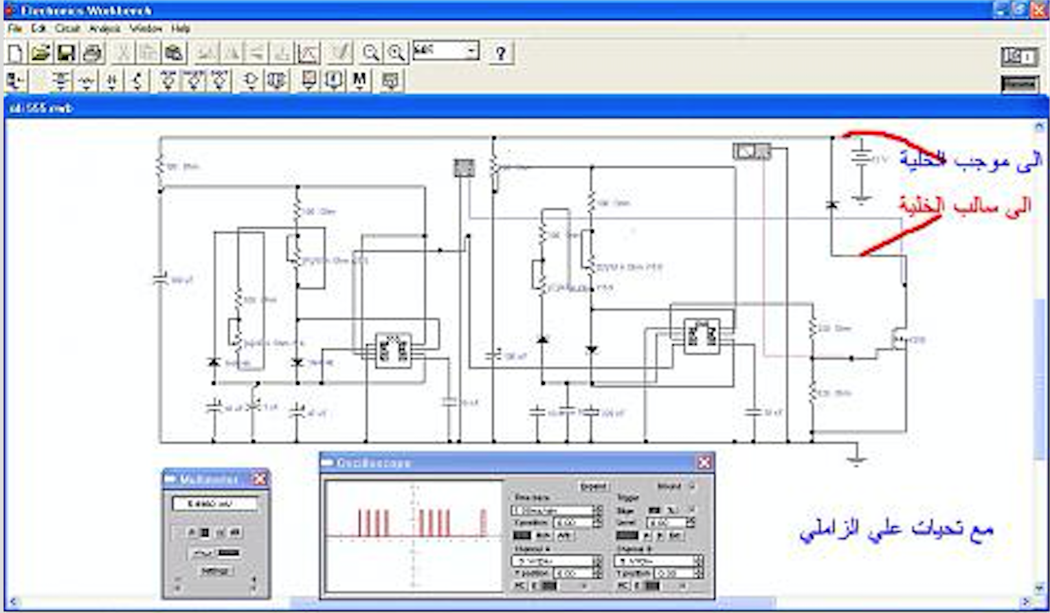
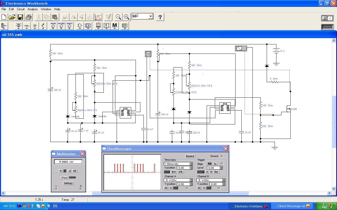
دائرة الرنين الكهربي اللتى تجعلك من اغنى الناس
السلام عليكم ورحمة الله وبركاته
هذا الموضوع ان تم اخذه على محمل اجدية فستكون صاحب مشروع يجعلك من اغنى الناس
تعلمون ان اصحاب شركات البترول من اغنى الناس وكذالك كل العملين فى هذا المجال من الطاقة
ونظرا لاهميته وعدم علم الكثييرين بالطاقة اللتى وضعها الله سبحانة وتعالى فى الماء
فقد جعل منه كل شئ حى و كل ماتتطلبه الحياة تجدة فيه
فسبحان الله العظيم وسبحان الله وبحمده
تم اكتشاف الطاقة فى الماء منذ مايزيد عن عشرين عاما ولهذا العلم من العلوم المحرمة على الشعوب
لانه لايعود بالنفع والمال على اصحاب شركات البترول واحتكارهم للاسعار
ولذا شاء الله تعالى ان يظهر الطاقة الموجودة بالماء
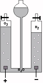
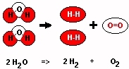
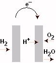
وقد اكتشفها العلم استانلى ماير عن طريق تعريض الما ء لترد من جهاز رنين كهربي يصدر موجات مربعة تقوم بتفكيك الماااااااااااء الى عنصريه الاساسيين الهيدروجين والاكسجين وادخالهم الى المحرك بدلا عن البنزين
ولكن للاسف تعم بعد فترة التعتيم عليه وقتل فى اسباب مجهولة
واليوم يعكف الكثير من شباب العلم على تصنيع تلك الدئرة وكل يبتكر ويستحدث شئيا جديدا بها
ولذا انتظر منكم ان تضعوا ابتكاراتكم لتلك الدوائر حتى تنتشر
ولا يحتفظ بالفكرة شخص ويختفى للابد كما حدث للكثيرين
فأن انتشرت الفكرة اصبحت فى امان ويمكنك تطوير الدائرة وتحديثها لبيعها ونجاح مشروعك
وهذة الدائرة تعمل على تحرير طاقة الماء
فأتمنى الا يتدخل احد بالسفسطة و الكلام اللذى لامعنى له الا المحافظة على مصالحه الشخصية وراسمالة من عمله فى مجال البترول
وسأقوم برفع بعض الحلول اللتى توصل لها اخوتكم من العرب والصور والافلام اللتى تساعد على انتاجها تباعا
فهذة دعوة للمشاركة الجادة لمصلحة المسلمين ولخدمتكم
مشكور أخي الكريم ولله كلمة شكر قليلة على هذه الفكرة القيمة التي ربما يكون فيها تغير لمسار أمور كثيرة ونتمنى من الله العلي القدير أن التوفيق لنا ولجميع الأخوة أن يكون لنا مشاركة في هذا الموضوع
والان مع الجديد على شبكة الانترنت
قائمة باسعار بيع تكل الدوائر على النتر نت مع صورها
I Repair INVERTERS!
Do you have an Inverter which is burned out or simply will not work? Why not have it fixed. Check my repair prices below:
10 Watt-100 Watt: $9.99
101 Watt-300Watt: $19.99
301 Watt-600Watt: $39.99
601 Watt-1000Watt: $59.99
1001 Watt-2000Watt: $69.99
2001 Watt-4000Watt: $89.99
4001 Watt-5000Watt: $99.99
5001 Watt-7000Watt: $139.99
7001 Watt-10000Watt: $199.99
Over 10000Watt - Contact Me
Power Supply Repairs
Prices vary, & never more than $89.99 for repair. Most cases, the cost is less. NON-Programmable PSUs ONLY.
وهذا سعرها $99.99
وطبعا ممكن تعرف المكسب كبير وحجمة من القطع الموجودة اللتى لاتساوى الخمسة دولاراتفهيا لمن ارد ان يتقدم ويصبح صاحب اكبر مشروع من نو
plitude in comparison with the sine and sawtooth waveforms. Check out the pictures below. This is the top of the circuit board. I used some non-coppered perfboard I had lying about to build the circuit on. Whenever I use perfboard, I like to mark up my perfboard with some fine point Sharpie markers and get all the connections worked out before I actually construct the circuit. I find it easier to do it this way. This is the back side. It’s a little more challenging using this type of perfboard over the copper padded type. Here is a view of the front. The enclosure comes from a defunct 4-way data switch box. I gutted it and created some graphics for the faceplate. It measures 7.5"x2.25"x5" deep. For the frequency range switch, I used a recycled rotary switch from an old parallel port A/B switch box. To make it work with this circuit, I had to disassemble it and rearrange the insides a little bit, but now it does exactly what I want it to. (I know, I could have just bought a new rotary switch, but I had this switch lying around…) Since I am using a single female BNC jack and a single 1/4" jack wired in parallel, I decided to use three SPST switches to switch between the different waveforms. One of the switches will be a on-center off-on type. I figure the middle position would make a nice “kill switch” which will prevent any waveforms from reaching the output jacks. I like the idea, because if I don’t want any output, I can just flip that switch and leave the unit powered up. Of course, one could just use another rotary switch with a SPST switch that could act as a kill switch as well. I used the SPST switches mainly because I had a bunch of them lying around waiting for a new home…
This homebrew function generator isn’t as fancy or accurate as the ones that are on the market, but for a do-it-yourselfer hobbyist type, it’s adequate. I have found that the sine wave isn’t totally accurate when I switch between frequency ranges, but I have incorporated a pot which corrects any waveform offsets, so it still quite useable and pretty accurate. Not too bad for a $20 project.
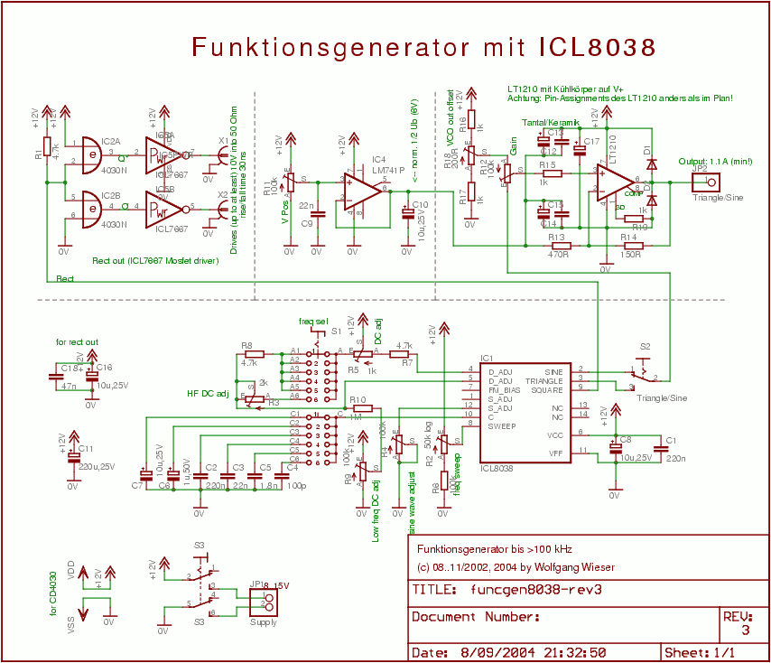
The circuit here presents an Oscillator featuring the following attributes:
[ul]
[li] 1.1A guaranteed output current for sine and triangle waves with thermal shutdown and protection diodes[/li][li] Variable offset and gain for the sine/triangle output[/li][li] CMOS-compatible complementary square wave outputs capable of driving into 50 Ohm with rise/fall times of 30ns at 10V (new in Rev 3).[/li][li] Frequency range 0.5Hz to 300 kHz (but signal degenerates when approaching the upper frequency limit)[/li][li] Single supply operation, 5V to 15V[/li] About 50% duty cycle (non-precision and adjustable via a trim pot)[/ul](This is the 3rd revision dated 09/2004.)
Circuit
The circuit is a fairly easy design: It consists of the actual VCO (ICL8038 with supplement parts), the sine and triangle output stage (LT1210) and the CMOS-compatible output stage using the MOSFET driver chip ICL7667. Download function generator circuit schematic:
Permission to copy and use this schematic is hereby granted provided credit is given where it is due.
The ICL8038 and all parts around on the lower half of the sheet make up the actual oscillator which is a modified design based on one of the application examples in Intersil’s data sheet. There is a large 6-stage switch (S1) to select the major frequency and a logarithmic potentiometer (R2) for minor frequency selection.
I discourage implementing the oscillator as shown in the above sheet because most of the other potentiometers turned out to be without significant enough effect on the output wave form to jusify their application. Furthermore, duty cycle adjustment will not keep a 50% ratio over all frequencies.
The switch S2 is used to choose between sine and triangle wave for the high-current amplifier.
The CD4030 on the left top is used as CMOS-logic signal preconditioning feeding the MOSFET driver IC ICL7667 as output stage for the complementary square wave output. The application of the two XOR gates has the advantage that it can supply a sqare wave and its complement without time offset between them (because CMOS has balanced raise and fall times). Use a bypass capacitor near the ICL7667 device as it can draw quite strong currents and is capable of driving into 50 Ohm up to at least 10V resulting in rise/fall times of 30ns. So, I’m now entirely satisfied with the digital output.
The industry-standard LM741 in combination with R11 is used to adjust the sine/triangle offset level. (Hint: You should probably use something better here - especially more output current cannot hurt.) Since this oscillator is single-supply, it comes handy that you can change the “zero level” of the wave output; you will normally adjust that to half of the supply voltage. R11 is meant to be available to the user.
The actual sine/triangle output amplifier was a bit hard to find because it should be able to drive 1A while still not degenerating signal wave form at some hundred kHz. After some searching, I found the ADSL line driver LT1210 from Linear Technology. Being an ADSL line driver, it has a high GBP and high slew rate while providing the required output current (1.1A guaranteed) at all frequencies in question. The part can be obtained e.g. from Bürklin.
It turned out that this quick current feedback amplifier required very good DC decoupling/bypassing capacitors in order not to start oscillating of its own (at frequencies up to 40MHz). It took me a lot of time to get it work properly; but once that is achieved, the amplifier shows very good performance. (Note: The current implementation is not yet perfect as I noted some months later: It may still start oscillating for parts of the period when driving some special loads.)
R18 is used to trim the VCO output offset from the ICL8038 (about half supply voltage). R12 is meant for the user as gain adjustment to tune the sine/triangle amplitude from zero to more than supply voltage (resulting in wave tips being cut off). The maximum gain is trimmed by R13/R14 and care sould be taken to use proper values (consult LT1210’s data sheet for details).
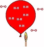
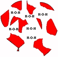
 قوة اللهب انظر الصورة