يحتوي الدرس على الأمثلة الأتية
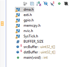
Data transfer example with memcpy32 using for loop and pointer arithmetic
DMA data transfer example using FIFO mode single transfer
Project files
L13_DMA_examples_01.zip (184.0% u)
يحتوي الدرس على الأمثلة الأتية
Data transfer example with memcpy32 using for loop and pointer arithmetic
DMA data transfer example using FIFO mode single transfer
Project files
L13_DMA_examples_01.zip (184.0% u)
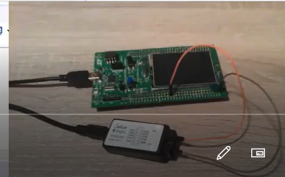
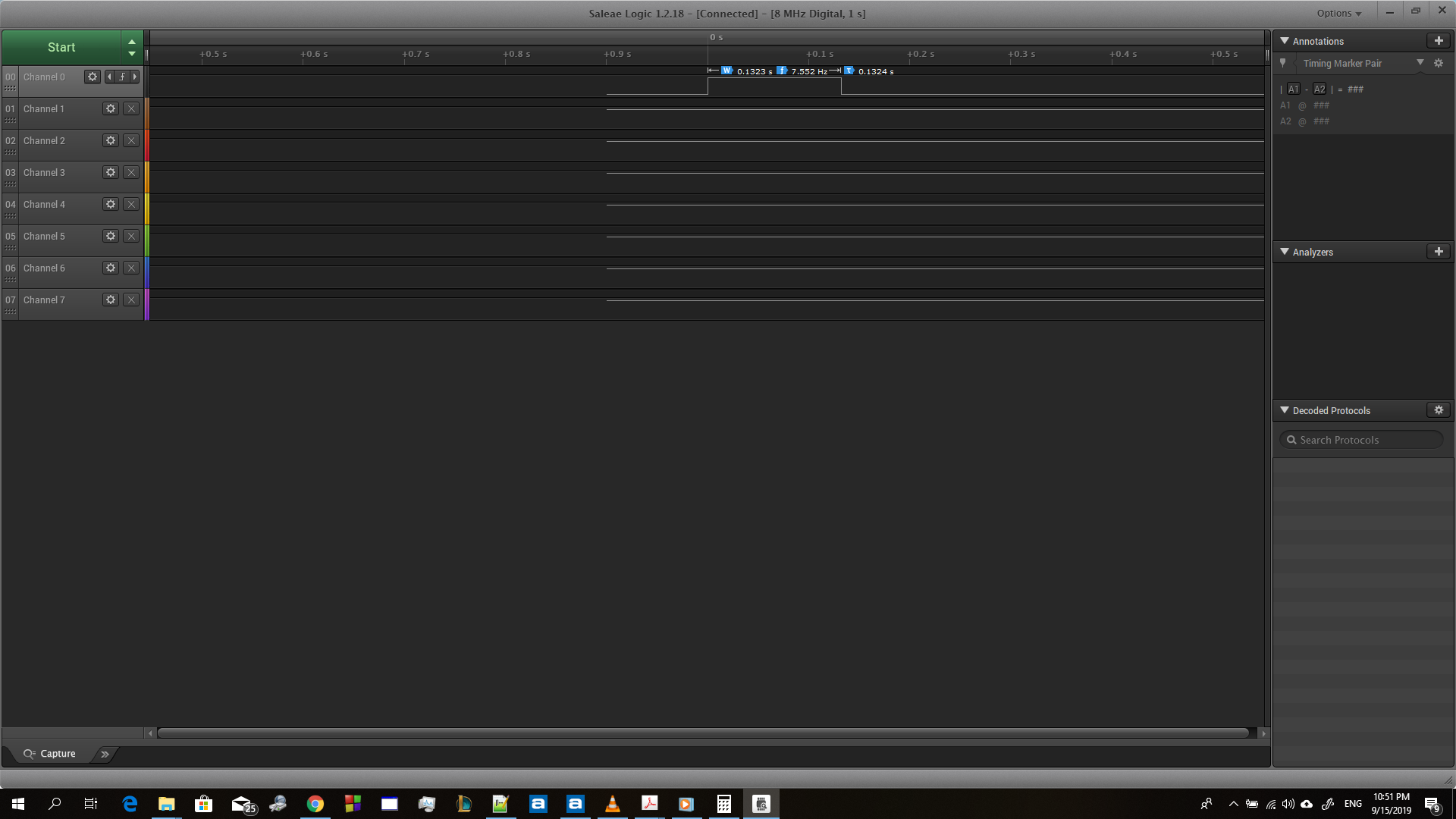
You can connect it to any pin as you want, just set the output high when you start and set it low when you finish, then you can measure the difference.
In the example, i connected the logic analyser to the green led output pin PG13.
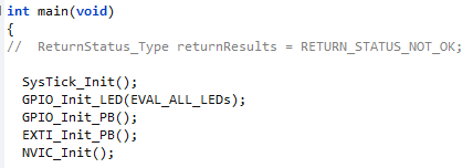
GPIO_Init_PB() function is used to configure the GPIO for leds, if you go inside this function you can see it uses PG13.
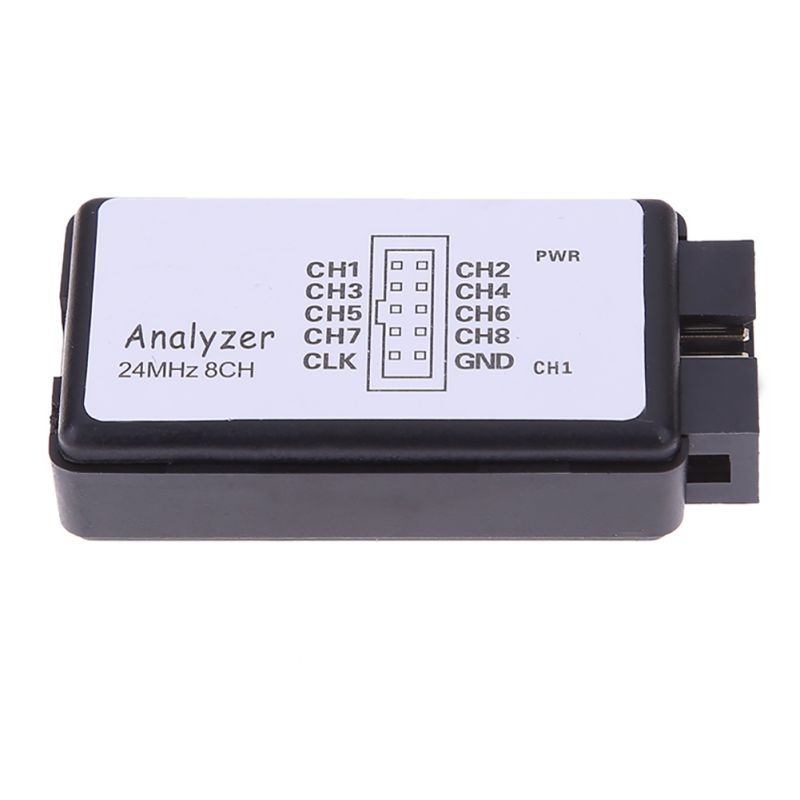
Sir for the Logic Analyzer you use the Channel 1 and the GND ? if i have three or four Channel how i can see it ( Visualize it ) and i have 1 GND Writed on Him GND CH1
This is a common ground for all channels.
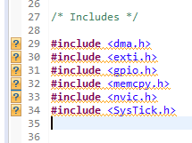
Right click on the include folder and select add/remove include path.
I used the analyzer and the example code however the width of the pulse was too much
what is the reason of this delay
thanks in advance
Maybe, you have different hardware, different processor speed or modified the example.
do you mean PC (processor ) or target processor
I am using the example code as it is and using the same target MC
If you are using the same code with the same target microcontroller, you should get the same results. I can not find any another reasone for difference, so i will doubt that something is wrong and you did not notice.